YOUR CART
- No products in the cart.
Subtotal:
$0.00
Click here to see detailed information about the product
| Manufacturer | Tides Marine |
|---|---|
| Product Code | WATERPICKUP |
| Product Line | INJT |
Price Price $29.44
Description
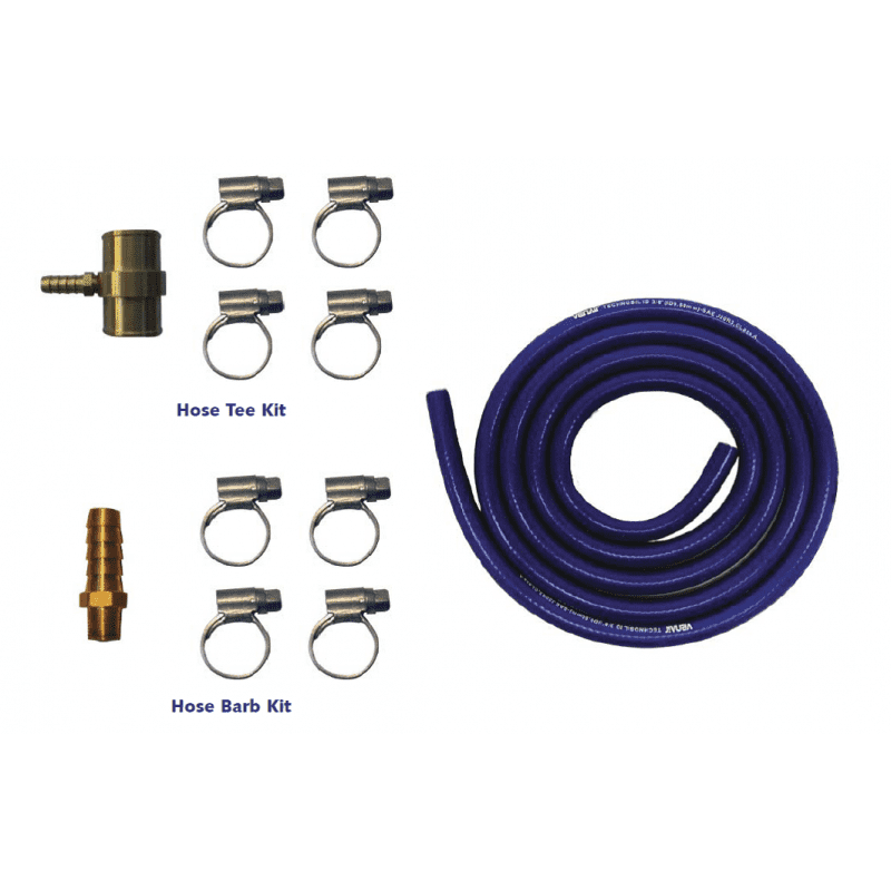
IJK250 375 2000 Water Pick-Up Kit consists of:
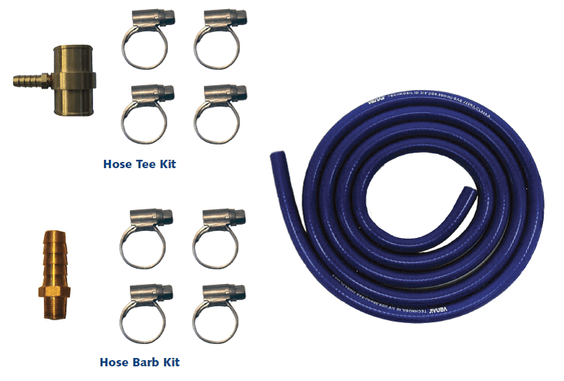
Tides Marine Water Pick-Up Kits include everything needed to connect SureSeals to a point in the engine’s raw water cooling system. This water is necessary for proper lubrication of the lip seal and PTFE bearing in the SureSeal housing. There are two types of kits available.
Hose Tee Kits are used to tap into flexible cooling hoses and Hose Tee Kits are used to tap into fixed points in the raw water cooling system. See diagram on the Before Ordering Page.
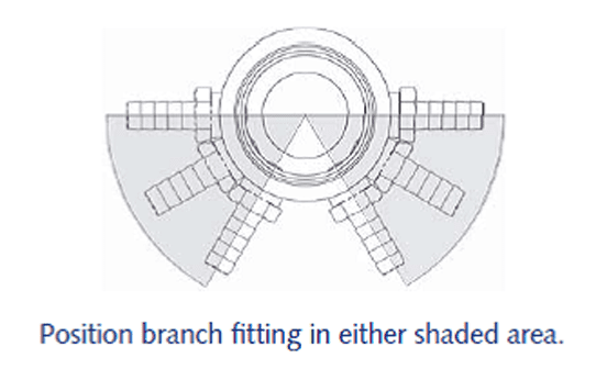
If you plan to use a hose tee, measure the inside diameter of the hose you will be using and match it to the corresponding number in the chart on the specification page. Note the overall length of the hose tee in this chart to make sure there is enough hose available for the connection.
Then, select the hose tee model with the branch fitting outside diameter that matches that of the water injection fi tting on your SureSeal.
SureSeals used on propeller shafts with an outside diameter up to and including 2 3/4” will have a 3/8” injection fitting. For shafts 3” and larger, the correct injection fitting is 1/2”.
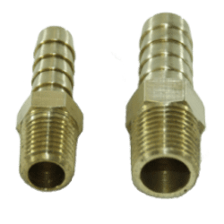
If you will be using a hose barb to complete your water pick-up system, remove the plug at the point on the engine you have selected and determine its thread size. Find the corresponding thread size in the chart on the specification page and choose the fitting with the hose barb dimension that matches your SureSeal.
When the engine (or engines) are located below the waterline OR water lift mufflers are installed, a vented loop may be required to prevent back-flooding of water through the exhaust system and into the engine(s). ABYC guidelines regarding vented loop materials and installation practices should be followed.
The water pick-up fitting should be installed in the “pressure side” of the vented loop “T”. This vented loop should be as far above the waterline as is practical (a minimum distance of 12” is required).
In twin engine applications using water lift mufflers, a check valve in each water pick-up line is required if a crossover line is installed.
Vented loops and check valves should be inspected for proper function at least twice a year. Read the SureSeal installation instructions provided with each SureSeal carefully before proceeding. If you have any questions, contact Tides Marine for assistance.
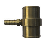
Hose Barb KitsHose barb kits contain a straight brass hose barb which can be threaded into any number of pick-up points in the water pump, gear cooler or heat exchanger. These hose barbs are sized to match the corresponding fitting on each SureSeal. The kit includes 8′ of marine grade silicone fuel hose and all necessary hose clamps. |
|
Please note that the use of hose barbs in the raw water cooling system requires good care during installation and additional maintenance once installed.
Sediment, engine scale, rust and other debris are prone to collect in such 90° turns.
Water pick-up hose should be routed from the pick-up point on the engine to the SureSeal® in a manner which eliminates / minimizes the possibility of chafing, burning or kinking. Turns made by the hose should be minimized to improve water flow.
Support clips / clamps / ties used to dress the hose should not be so tight as to crush the hose / restrict water flow.
Tides also recommends that a bit of slack be left in the hose near the SureSeal® to allow for some movement. This will minimize loading of the SureSeal® on the shaft during normal vessel operation.

| Hose Inside Diameter A | Hose Tee Length B | Branch Hose Barb Size C | Part Number | Buy Online |
|---|---|---|---|---|
| 3/8 | 1 7/8 | 3/8 | TK0375-3/8-.275 | Buy Now |
| 5/8 | 1 7/8 | 3/8 | TK0625-3/8-.218 | Buy Now |
| 3/4 | 1 7/8 | 3/8 | TK0750-3/8-.218 | Buy Now |
| 1 1/4 | 1 7/8 | 3/8 | TK1250-3/8-.218 | Buy Now |
| 1 1/2 | 1 7/8 | 3/8 | TK1500-3/8-.218 | Buy Now |
| 1 5/8 | 1 7/8 | 3/8 | TK1625-3/8-.218 | Buy Now |
| 1 3/4 | 2 | 3/8 | TK1750-3/8-.218 | Buy Now |
| 2 | 2 1/2 | 3/8 | TK2000-3/8-.218 | Buy Now |
The following is a brief overview of the typical installation procedure. BE SURE TO FOLLOW THE INSTRUCTIONS INCLUDED WITH EACH KIT. Failure to follow the instructions could result in damage to the SureSeal or your engine.
3A. If using a threaded fitting-type pick-up, remove the appropriate plug or drain. Using a small screwdriver or awl, poke/scrape the inside of the opening to dislodge or remove any engine scale, sediment, debris, etc. which could clog the line. Coat the threads of the fitting with sealant and install.
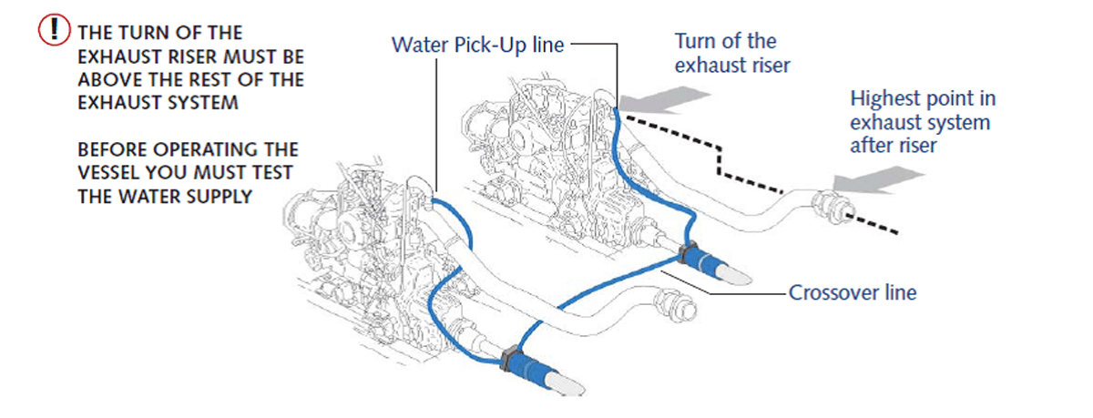
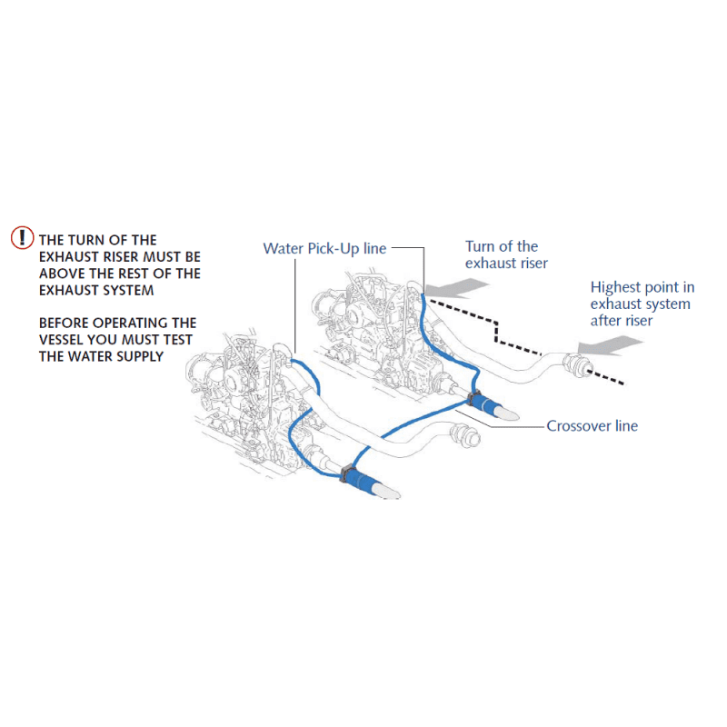
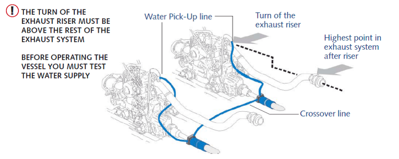
6A. For twin-engine applications, we recommened the use of a crossover line between port and starboard SureSeals to insure proper lubrication and cooling water to both seals in the event that only one engine is running. Before installing a crossover line, you must inspect the vessel’s raw water exhaust system. DO NOT USE A CROSSOVER LINE if the highest point in the exhaust system is above the turn of the exhaust riser. “back flow” could occur while running on only one engine causing serious damage to the other engine/turbo. For all Crossover setups, a second fitting is required on each SureSeal.
8A. To test a “Double Injection” set-up, remove the crossover hose from one SureSeal. Cap the injection fitting as described above. Start the other engine and run in neutral. Hold the end of the crossover hose above the level at which the cooling system water enters the manifold. A steady flow of water indicates there is suffcient pressure for proper function. Reconnect the hose and repeat the process for the other engine. Dress the crossover hose and secure with cable ties (loosely).
Water Pick-Up Kits may be ordered online. Buy Now
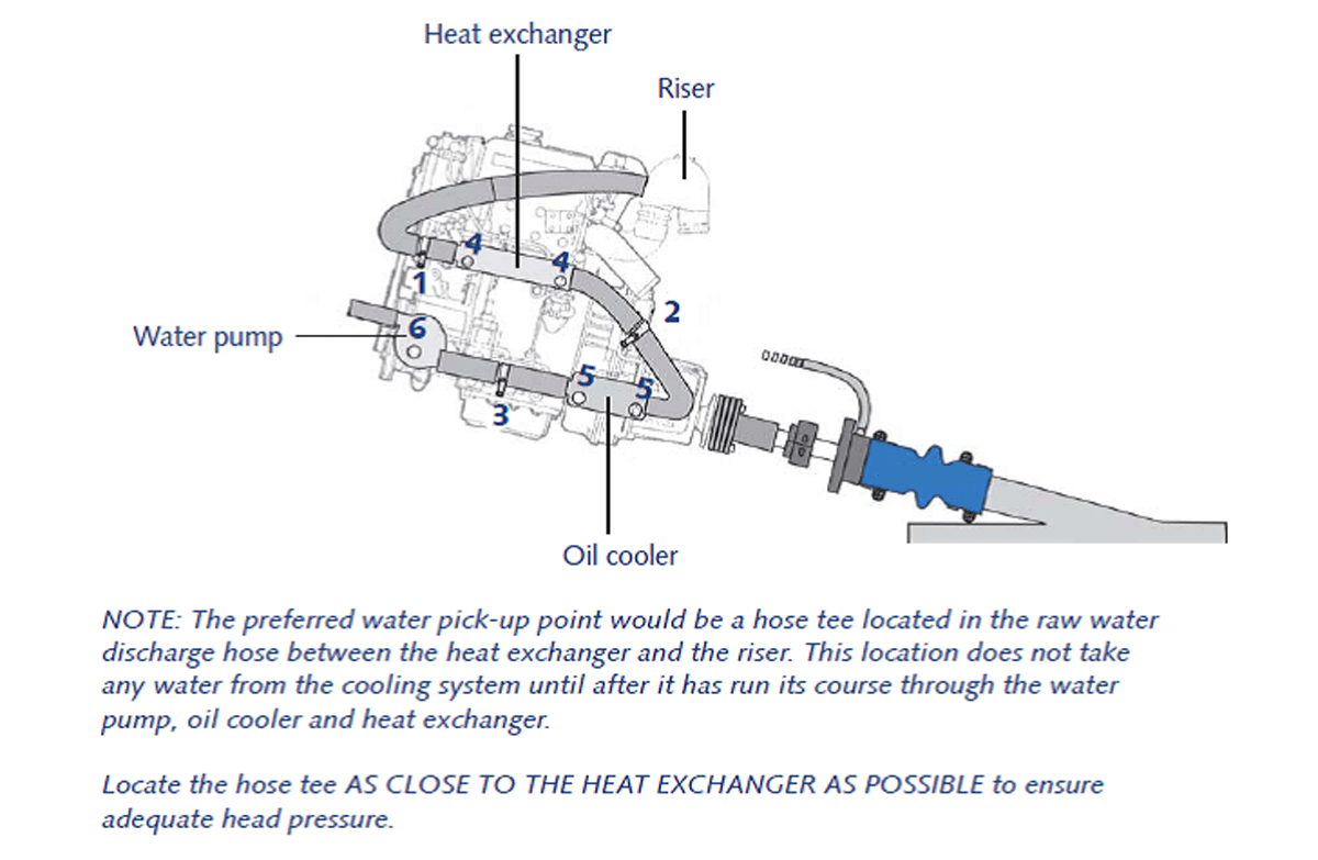
To determine which water pick-up kit to order, first identify the point in the engine’s raw water cooling system from which you plan to take the water for your SureSeal.
Click here to Download Complete Water Pick-up Kit Installation Instructions.
Select at least 2 products
to compare